Sensores:
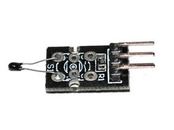
- Temperature sensor module KY-001
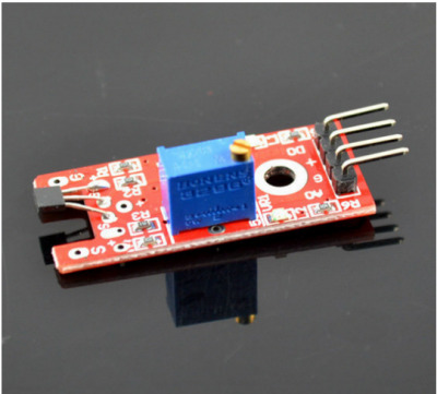
- Vibration switch module KY-002
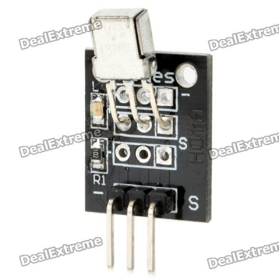
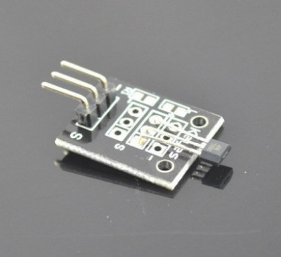
- Hall magnetic sensor module KY-003
- Key switch module KY-004
- Infrared Transmitter Module KY-005
- Small passive buzzer module KY-006
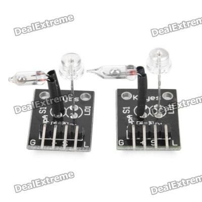
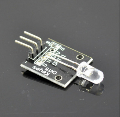
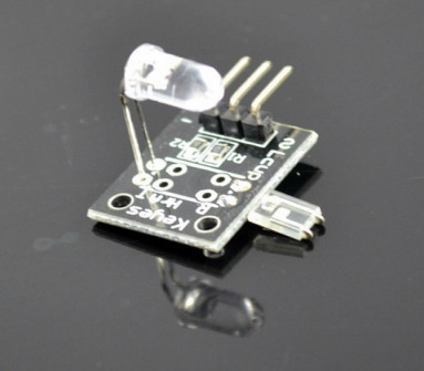
- Laser sensor module KY-008
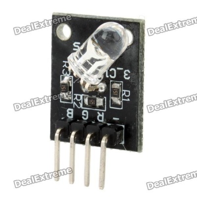
- 3-color full-color LED SMD modules KY-009
- Optical broken module KY-010
- 2-color LED module KY-011
- Active buzzer module KY-012
- Temperature sensor module KY-013
- Temperature and humidity sensor module KY-015
- 3-color LED module KY-016
- Mercury open optical module KY-017
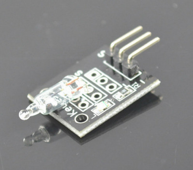
- Photo resistor module KY-018
- 5V relay module KY-019
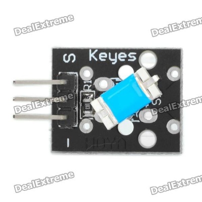
- Tilt switch module KY-020
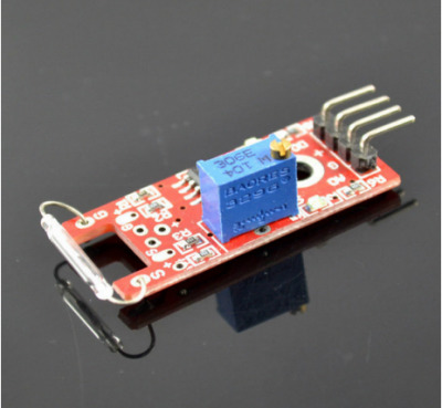
- Mini magnetic reed modules KY-021
- Infrared sensor receiver module KY-022
- XY-axis joystick module KY-023
- Linear magnetic Hall sensors KY-024
- Reed module KY-025
- Flame sensor module KY-026
- Magic light cup module KY-027
- Temperature sensor module KY-028
- Yin Yi 2-color LED module 3MM KY-029
- Hit sensor module KY-031
- Obstacle avoidance sensor module KY-032
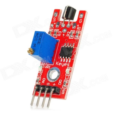
- Hunt sensor module KY-033
- Automatic flashing colorful LED module KY-034
- Class Bihor magnetic sensor KY-035
- Metal touch sensor module KY-036
- Sensitive microphone sensor module KY-037
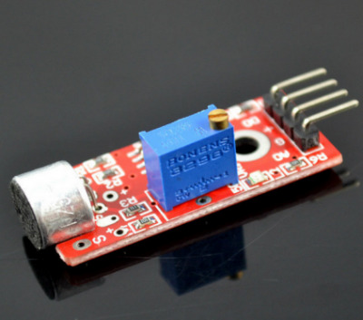
- Microphone sound sensor module KY-038
- Detect the heartbeat module KY-039
- Rotary encoder module KY-040
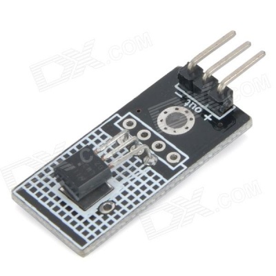
Temperature sensor module KY-001
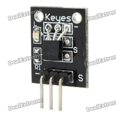
Features:
- Resistant to wear and touch, small size, easy to use, suitable for narrow space equipment digital temperature measurement
- Temperature range: -55 ° C to +125 ° C
- Temperature resolution of 0.5 ° C
- Support multi-point network function
- Power: 5V DC
Connections:
- Pin - = connect to Arduino GND
- Pin (middle) = connect to arduino +5V
- Pin S = Signal, in this example connect to Arduino Digital port 10
When everything is properly connected, there is a led on the module that blinks when the sensor is read.
#include <OneWire.h>

// DS18S20 Temperature chip i/o
OneWire ds(10);  // on pin 10

void setup() {
  // initialize inputs/outputs
  // start serial port
  Serial.begin(9600);
}

void loop() {

  //For conversion of raw data to C
  int HighByte, LowByte, TReading, SignBit, Tc_100, Whole, Fract;

  byte i;
  byte present = 0;
  byte data[12];
  byte addr[8];

  if ( !ds.search(addr)) {
      Serial.print("No more addresses.\n");
      ds.reset_search();
      return;
  }

  Serial.print("R=");
  for( i = 0; i < 8; i++) {
    Serial.print(addr[i], HEX);
    Serial.print(" ");
  }

  if ( OneWire::crc8( addr, 7) != addr[7]) {
      Serial.print("CRC is not valid!\n");
      return;
  }

  if ( addr[0] == 0x10) {
      Serial.print("Device is a DS18S20 family device.\n");
  } else if ( addr[0] == 0x28) {
      Serial.print("Device is a DS18B20 family device.\n");
  } else {
      Serial.print("Device family is not recognized: 0x");
      Serial.println(addr[0],HEX);
      return;
  }

  ds.reset();
  ds.select(addr);
  ds.write(0x44,1);         // start conversion, with parasite power on at the end

  delay(1000);     // maybe 750ms is enough, maybe not
  // we might do a ds.depower() here, but the reset will take care of it.

  present = ds.reset();
  ds.select(addr);
  ds.write(0xBE);         // Read Scratchpad

  Serial.print("P=");
  Serial.print(present,HEX);
  Serial.print(" ");
  for ( i = 0; i < 9; i++) {           // we need 9 bytes
    data[i] = ds.read();
    Serial.print(data[i], HEX);
    Serial.print(" ");
  }
  Serial.print(" CRC=");
  Serial.print( OneWire::crc8( data, 8), HEX);
  Serial.println();

  //Conversion of raw data to C
  LowByte = data[0];
  HighByte = data[1];
  TReading = (HighByte << 8) + LowByte;
  SignBit = TReading & 0x8000;  // test most sig bit
  if (SignBit) { // negative
    TReading = (TReading ^ 0xffff) + 1; // 2's comp
  }
  Tc_100 = (6 * TReading) + TReading / 4;    // multiply by (100 * 0.0625) or 6.25

  Whole = Tc_100 / 100;  // separate off the whole and fractional portions
  Fract = Tc_100 % 100;

  if (SignBit) { // If its negative
     Serial.print("-");
  }
  Serial.print(Whole);
  Serial.print(".");
  if (Fract < 10) {
     Serial.print("0");
  }
  Serial.print(Fract);

  Serial.print("\n");
  //End conversion to C
}
Links:
Vibration switch module KY-002
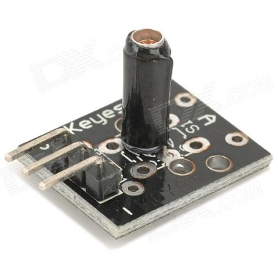
Features:
Connections:
- Pin - = GND, connect to GND of the Arduino
- Pin (middle pin) +5 v, connect to Arduino +5
- Pin S signal, connect to Arduino pin 10
When there is vibration the Arduino LED on pin 13 flashes.
int led = 13 ;// define LED Interface
int shock = 10; // define the vibration sensor interface
int val; // define numeric variables val
void setup() {
  pinMode(led, OUTPUT) ; // define LED as output interface
  pinMode(shock, INPUT) ; // output interface defines vibration sensor
}

void loop() {
  val = digitalRead(shock) ; // read digital interface is assigned a value of 3 val
  if (val == HIGH) { // When the shock sensor detects a signal, LED flashes
    digitalWrite(led, LOW);
  } else {
    digitalWrite(led, HIGH);
  }
}
Links:
Hall magnetic sensor module KY-003
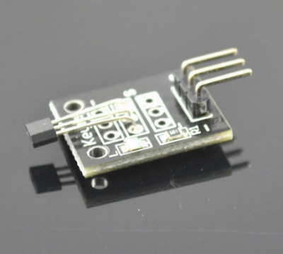
Features:
Connections:
- Pin - = GND, connect to GND of the Arduino
- Pin (middle pin) +5 v, connect to Arduino +5
- Pin S signal, connect to Arduino pin 10
- Power consumption, 3 mA in rest, 8 mA when switched on
/*
KY-003 Hall magnetic switch
*/

int Led = 13 ; // define LED Interface
int SENSOR = 10 ; // define the Hall magnetic sensor interface
int val ; // define numeric variables val

void setup() {
  pinMode(Led, OUTPUT) ;    // define LED as output interface
  pinMode(SENSOR, INPUT) ;  // define the Hall magnetic sensor line as input
}

void loop() {
  val = digitalRead(SENSOR) ; // read sensor line
  if (val == LOW) { // when the Hall sensor detects a magnetic field, Arduino LED lights up
    digitalWrite(Led, HIGH);
  } else {
    digitalWrite(Led, LOW);
  }
}
Key switch module KY-004
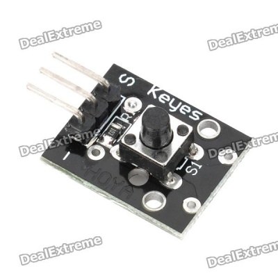
Features:
Connections:
- Pin - = GND, connect to GND of the Arduino
- Pin (middel pin) +5 v, connect to Arduino +5
- Pin S signal, connect to Arduino pin 10
int Led = 13 ;// define LED Interface
int buttonpin = 10; // define the key switch sensor interface
int val ;// define numeric variables val
void setup() {
  pinMode(Led, OUTPUT); // define LED as output interface
  pinMode(buttonpin, INPUT); // define the key switch sensor output interface
}
void loop() {
  val = digitalRead(buttonpin); // digital interface will be assigned a value of 3 to read val
  if (val == HIGH) { // When the key switch when the sensor detects a signal, LED flashes
    digitalWrite(Led, HIGH);
  } else {
    digitalWrite(Led, LOW);
  }
}
Infrared Transmitter Module KY-005
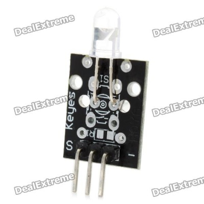
Features:
Connections:
Arduino controller × 1 USB data cable × 1 the infrared transmitter module × 1 the infrared receiver module × 1 Here follow the above means to build our test circuit Well, the whole test code is not long, we understand the code for those specific function of usage, then a Cut will become simpler, Come. Another point I must say is: we see the physical map will know, this used a two Arduino Board, the above code in the download time do to make it clear which is the launch, which was received? The program also Have noted, if the download is wrong, is not getting the results! Code download is complete, we open the Serial Monitor window, if you can see the following data show that It shows you are successful, ^ _ ^ From the receiving part of the code
#include <IRremote.h>
int RECV_PIN = 11; / / define input pin on Arduino
IRrecv irrecv (RECV_PIN);
decode_results results;
void setup() {
  Serial.begin(9600);
  irrecv.enableIRIn (); / / Start the receiver
}
void loop() {
  if (irrecv.decode (& results)) {
    Serial.println(results.value, HEX);
    irrecv.resume (); / / Receive the next value
  }
}
//Main emission part of the code:
#include <IRremote.h>
IRsend irsend;
void setup() {
  Serial.begin(9600);
}
void loop() {
  for (int i = 0; i <50; i + +) {
    irsend.sendSony (0xa90, 12); / / Sony TV power code
    delay(40);
  }
}
Small passive buzzer module KY-006

No oscillation source,need square wave(frequency 2K-5K ) to drive Audion 9012 drive; Work Voltage: 3.3-5V Set bolt hole,easy to assemble PCB Dimension: 3.3cm*1.3cm
Pin Definition:
- Pin: definition
- Vcc: 3.3~5V
- GND: the Ground
- I/O: I/O interface of SCM
//Example Code for KY-006

int buzzer = 8 ;// setting controls the digital IO foot buzzer
void setup() {
  pinMode(buzzer, OUTPUT) ;// set the digital IO pin mode, OUTPUT out of Wen
}
void loop() {
  unsigned char i, j ;// define variables
  while (1)   {
    for (i = 0; i <80; i++) { // Wen a frequency sound
      digitalWrite(buzzer, HIGH) ;// send voice
      delay(1) ;// Delay 1ms
      digitalWrite(buzzer, LOW) ;// do not send voice
      delay(1) ;// delay ms
    }
    for (i = 0; i <100; i++) { // Wen Qie out another frequency sound
      digitalWrite(buzzer, HIGH) ;// send voice
      delay(2) ;// delay 2ms
      digitalWrite(buzzer, LOW) ;// do not send voice
      delay(2) ;// delay 2ms
    }
  }
}
Laser sensor module KY-008
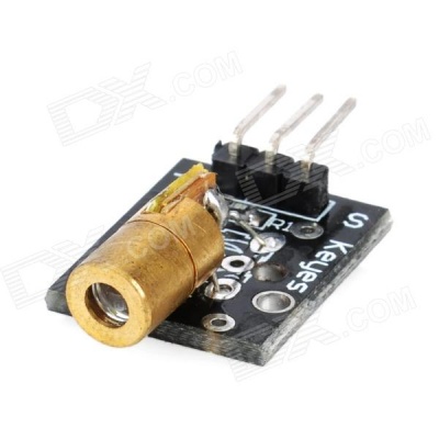
- Pin - = GND
- Pin (middle pin) = not connected
- Pin S = +5V
void setup() {
   pinMode(13, OUTPUT); // define the digital output interface 13 feet
}

void loop() {
  digitalWrite(13, HIGH); // open the laser head
  delay(1000); // delay one second
  digitalWrite(13, LOW); // turn off the laser head
  delay(1000); // delay one second
}
Links:
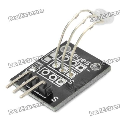
3-color full-color LED SMD modules KY-009
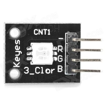
Since you can't connect the led's directly to the Arduino you will need resistors!!
- Arduino pin 9 --> 180 Ohm resistor --> Pin 'R' of KY-009 module
- Arduino pin 10 --> 100 Ohm resistor --> Pin 'G' of KY-009 module
- Arduino pin 11 --> 100 Ohm resistor --> Pin 'B' of KY-009 module
- Arduino GND --> pin '-' of KY-009 module
int redpin = 11; // select the pin for the red LED
int bluepin = 10; // select the pin for the blue LED
int greenpin = 9; // select the pin for the green LED
int val=0;
void setup() {
  pinMode(redpin, OUTPUT);
  pinMode(bluepin, OUTPUT);
  pinMode(greenpin, OUTPUT);
  Serial.begin(9600);
}

void loop() {
  for (val=255; val>0; val--) {
    analogWrite(11, val);
    analogWrite(10, 255-val);
    analogWrite(9, 128-val);
    delay(1);
  }
  for (val = 0; val <255; val++) {
    analogWrite(11, val);
    analogWrite(10, 255-val);
    analogWrite(9, 128-val);
    delay(1);
  }
  Serial.println(val, DEC);
}
Optical broken module KY-010
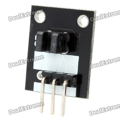
Features:
- Left = Ground
- Middle = +5V
- Right = Signal
- Connect the module to the arduino as follows:
- Arduino pin GND to module GND
- Arduino digital pin 3 to module Signal
- Arduino pin 5V to module 5V
// Example code for KY-010
// photo interrupter module

int Led = 13 ;// define LED Interface
int buttonpin = 3; // define the photo interrupter sensor interface
int val ;// define numeric variables val
void setup() {
  pinMode(Led, OUTPUT) ;// define LED as output interface
  pinMode(buttonpin, INPUT) ;// define the photo interrupter sensor output interface
}
void loop() {
  val = digitalRead(buttonpin) ;// digital interface will be assigned a value of 3 to read val
  if (val == HIGH) { // When the light sensor detects a signal is interrupted, LED flashes
    digitalWrite(Led, HIGH);
  } else {
    digitalWrite(Led, LOW);
  }
}
Links úteis:
2-color LED module KY-011
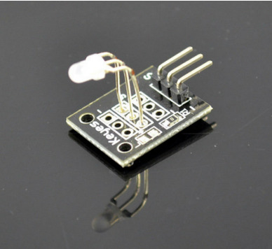
Features:
- Color: Green, Red
- Diameter: 5mm
- Case Color: None
- Package Type: Diffusion
- Voltage (V) :2.0 - 2.5
- Using a current (mA): 10
- Viewing angle: 150
- Wavelength (nm): 571, 644
- Luminous intensity (MCD) :20-40, 40-80
Stent type: long-legged
Arduino pin 10 --> resistor 330 Ohm --> Signal pin of the module
- Arduino pin 11 --> resistor 330 Ohm --> Middel pin of the module
- Arduino GND --> module -/GND
// Arduino test code for KY011
int redpin = 11; // select the pin for the red LED
int greenpin = 10; // select the pin for the green LED
int val;
void setup() {
   pinMode(redpin, OUTPUT);
   pinMode(greenpin, OUTPUT);
}
void loop() {
   for (val = 255; val> 0; val--) {
      analogWrite(greenpin, val);
      analogWrite(redpin, 255-val);
      delay(15);
   }
   for (val = 0; val <255; val++) {
      analogWrite(greenpin, val);
      analogWrite(redpin, 255-val);
      delay(15);
   }
}
Active buzzer module KY-012
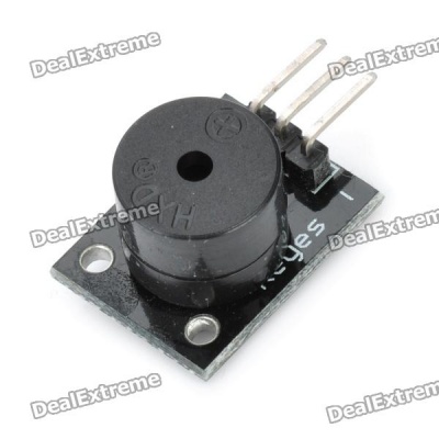
- Module pin - = GND Module pin S = +5V
- Connection to Arduino
- Arduino digital pin 8 --> Module pin S
- Arduino GND --> Module pin -
//Example code KY012 active buzzer
int speakerPin = 8;
void setup() {
  pinMode(speakerPin, OUTPUT);
}

void loop() {
  analogWrite(speakerPin, 255);
  delay(50);
  analogWrite(speakerPin, 0);
  delay(10);
}
Temperature sensor module KY-013
- Arduino pin analoog A5 --> module S (Signal)
- Arduino pin GND - module -
- Arduino pin 5+ --> middel pin 5V
#include <math.h>

int sensorPin = A5; // select the input pin for the potentiometer

double Thermistor(int RawADC) {
  double Temp;
  Temp = log(10000.0*((1024.0/RawADC-1)));
  Temp = 1 / (0.001129148 + (0.000234125 + (0.0000000876741 * Temp * Temp ))* Temp );
  Temp = Temp - 273.15;            // Convert Kelvin to Celcius
   //Temp = (Temp * 9.0)/ 5.0 + 32.0; // Convert Celcius to Fahrenheit
   return Temp;
}

void setup() {
  Serial.begin(9600);
}

void loop() {
  int readVal=analogRead(sensorPin);
  double temp =  Thermistor(readVal);

  Serial.println(temp);  // display tempature
  //Serial.println(readVal);  // display tempature
  delay(500);
}
Temperature and humidity sensor module KY-015
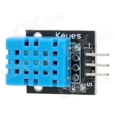
- Arduino pin 8 --> Pin S module
- Arduino GND --> Pin - module
- Arduino +5V --> Pin Middle
//KY015 DHT11 Temperature and humidity sensor
int DHpin = 8;
byte dat [5];
byte read_data () {
  byte data;
  for (int i = 0; i < 8; i ++) {
    if (digitalRead(DHpin) == LOW) {
      while (digitalRead(DHpin) == LOW); // wait for 50us
      delayMicroseconds (30); // determine the duration of the high level to determine the data is '0 'or '1'
      if (digitalRead(DHpin) == HIGH)
        data |= (1 << (7-i)); // high front and low in the post
      while (digitalRead(DHpin) == HIGH); // data '1 ', wait for the next one receiver
    }
  }
  return data;
}

void start_test () {
  digitalWrite(DHpin, LOW); // bus down, send start signal
  delay(30); // delay greater than 18ms, so DHT11 start signal can be detected

  digitalWrite(DHpin, HIGH);
  delayMicroseconds (40); // Wait for DHT11 response

  pinMode(DHpin, INPUT);
  while (digitalRead(DHpin) == HIGH);
  delayMicroseconds (80); // DHT11 response, pulled the bus 80us
  if (digitalRead(DHpin) == LOW);
  delayMicroseconds (80); // DHT11 80us after the bus pulled to start sending data

  for (int i = 0; i < 4; i ++) // receive temperature and humidity data, the parity bit is not considered
    dat[i] = read_data ();

  pinMode(DHpin, OUTPUT);
  digitalWrite(DHpin, HIGH); // send data once after releasing the bus, wait for the host to open the next Start signal
}

void setup() {
  Serial.begin(9600);
  pinMode(DHpin, OUTPUT);
}

void loop() {
  start_test();
  Serial.print("Current humdity =");
  Serial.print(dat [0], DEC); // display the humidity-bit integer;
  Serial.print('.');
  Serial.print(dat [1], DEC); // display the humidity decimal places;
  Serial.println('%');
  Serial.print("Current temperature =");
  Serial.print(dat [2], DEC); // display the temperature of integer bits;
  Serial.print('.');
  Serial.print(dat [3], DEC); // display the temperature of decimal places;
  Serial.println('C');
  delay(700);
}
3-color LED module KY-016
- Arduino pin 11 --> Pin R module
- Arduino pin 10 --> Pin G module
- Arduino pin 9 --> Pin B module
- Arduino pin GND --> Pin - module
- You don't need any resistors, these are already included on the module.
//KY016 3-color LED module
int redpin = 11; // select the pin for the red LED
int bluepin = 10; // select the pin for the blue LED
int greenpin = 9 ;// select the pin for the green LED
int val;

void setup() {
  pinMode(redpin, OUTPUT);
  pinMode(bluepin, OUTPUT);
  pinMode(greenpin, OUTPUT);
  Serial.begin(9600);
}

void loop() {
  for (val = 255; val> 0; val --) {
    analogWrite(11, val);
    analogWrite(10, 255-val);
    analogWrite(9, 128-val);
    delay(10);
    Serial.println(val, DEC);
  }
  for (val = 0; val <255; val ++) {
    analogWrite(11, val);
    analogWrite(10, 255-val);
    analogWrite(9, 128-val);
    delay(10);
    Serial.println(val, DEC);
  }
}
Mercury open optical module KY-017
- Arduino GND --> Pin - of module
- Arduino +5V --> Pin middel of module
- Arduino 3 --> pin S of module
//KY017 Mercury open optical module
int Led = 13 ;// define LED Interface
int buttonpin = 3; // define the mercury tilt switch sensor interface
int val ;// define numeric variables val
void setup() {
  pinMode(Led, OUTPUT) ;// define LED as output interface
  pinMode(buttonpin, INPUT) ;// define the mercury tilt switch sensor output interface
}
void loop() {
  val = digitalRead(buttonpin) ;// read the values assigned to the digital interface 3 val
  if (val == HIGH) { // When the mercury tilt switch sensor detects a signal, LED flashes
    digitalWrite(Led, HIGH);
  } else {
    digitalWrite(Led, LOW);
  }
}
- http://henrysbench.capnfatz.com/henrys-bench/keyes-ky-017-arduino-mercury-tilt-switch-tutorial/
- Arduino - Switching light on/off with Mercury Switch Module KY-017
Photo resistor module KY-018
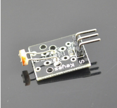
- Arduino A5 --> Module Signal (S)
- Arduino 5V --> Module +5V (Pin2)
- Arduino GND --> Module GND (-)
//KY018 Photo resistor module

int sensorPin = A5; // select the input pin for the potentiometer
int ledPin = 13; // select the pin for the LED
int sensorValue = 0; // variable to store the value coming from the sensor

void setup() {
  pinMode(ledPin, OUTPUT);
  Serial.begin(9600);
}

void loop() {
  sensorValue = analogRead(sensorPin);
  digitalWrite(ledPin, HIGH);
  delay(sensorValue);
  digitalWrite(ledPin, LOW);
  delay(sensorValue);
  Serial.println(sensorValue, DEC);
}
5V relay module KY-019
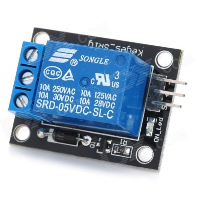
- 5V relay
- can be use for MCU
- TTL control signal is 5V-12V
- It can control AC or DC.can connect to 220VAC loader
- one OP and one ON
- power apply indicator
- control indicator
- Arduino digital pin 10 --> module pin S
- Arduino GND --> module pin -
- Arduino +5V --> module pin +
//KY019 5V relay module
int relay = 10; // relay turns trigger signal - active high;
void setup() {
  pinMode(relay, OUTPUT); // Define port attribute is output;
}

void loop() {
  digitalWrite(relay, HIGH); // relay conduction;
  delay(1000);
  digitalWrite(relay, LOW); // relay switch is turned off;
  delay(1000);
}
Program Description: The program notes in the conduction and disconnection refers to the way that we want that we are using the NO side, When S relay switches into high and hit the NO side, the switch is turned on, connected to the LED will be lit, otherwise the switch Hit the NC side, NO direction disconnect, LED light goes out; You will see the test results led lights flashing interval 1s;
in Description below Description: COM to VCC, NO then we have to control the LED anode, which Like when the relay turns on, LED lights will be lit; To complete the look of this test must be prepared to what what they specifically
- Arduino controller × 1
- USB data cable × 1
- 1 relay module × 1
- Led indicator × 1
- The resistance of the resistance 330 × 1
Of course, we have the following physical connections for a specific reference
Tilt switch module KY-020
int Led = 13 ;// define LED Interface
int buttonpin = 3; // define the tilt switch sensor interfaces
int val ;// define numeric variables val

void setup() {
  pinMode(Led, OUTPUT) ;// define LED as output interface
  pinMode(buttonpin, INPUT) ;//define the output interface tilt switch sensor
}

void loop() {
  val = digitalRead(buttonpin) ;// digital interface will be assigned a value of 3 to read val
  if (val == HIGH) { //When the tilt sensor detects a signal when the switch, LED flashes
    digitalWrite(Led, HIGH);
  } else {
    digitalWrite(Led, LOW);
  }
}
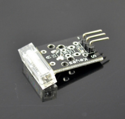
Mini magnetic reed modules KY-021
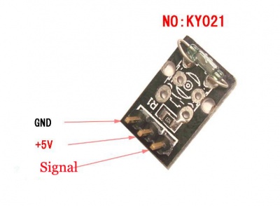
- Arduino GND --> Module pin -
- Arduino +5V --> Module PLUS (middle pin)
- Arduino Digital pin 3 --> Module S
//
// Example code for sensor KY021
// More info on http://tkkrlab.nl/wiki/Arduino_KY-021_Mini_magnetic_reed_modules
//
int Led = 13 ;// define LED Interface
int buttonpin = 3; // define the Reed sensor interfaces
int val ;// define numeric variables val

void setup() {
  pinMode(Led, OUTPUT) ;// define LED as output interface
  pinMode(buttonpin, INPUT) ;// output interface as defined Reed sensor
}

void loop() {
  val = digitalRead(buttonpin) ;// digital interface will be assigned a value of 3 to read val
  if (val == HIGH) { // When the Reed sensor detects a signal, LED flashes
    digitalWrite(Led, HIGH);
  } else {
    digitalWrite(Led, LOW);
  }
}
Infrared sensor receiver module KY-022
- Arduino GND --> Module pin -
- Arduino +5V --> Module PLUS (middle pin)
- Arduino Digital pin 11 --> Module S
/*
 * IRremote: IRrecvDemo - demonstrates receiving IR codes with IRrecv
 * An IR detector/demodulator must be connected to the input RECV_PIN.
 * Version 0.1 July, 2009
 * Copyright 2009 Ken Shirriff
 * http://arcfn.com
 */

#include <IRremote.h>

int RECV_PIN = 11;

IRrecv irrecv(RECV_PIN);

decode_results results;

void setup() {
  Serial.begin(9600);
  irrecv.enableIRIn(); // Start the receiver
}

void loop() {
  if (irrecv.decode(&results)) {
    Serial.println(results.value, HEX);
    irrecv.resume(); // Receive the next value
  }
}
XY-axis joystick module KY-023
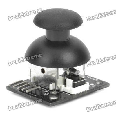
- Arduino GND --> Module pin -
- Arduino +5V --> Module pin +5V
- Arduino Analoog 0 --> Module VRx
- Arduino Analoog 1 --> Module VRy
- Arduino Digital --> Resistor??-->Module SW
- you need a resistor, you can use Arduino internal pullup resistor, Instruccion (pimode(pin, INPUT_PULLUP);) does the job
// Module KY023
// For more info see http://tkkrlab.nl/wiki/Arduino_KY-023_XY-axis_joystick_module
int JoyStick_X = A0; // x
int JoyStick_Y = A1; // y
int JoyStick_Z = 3; // key

void setup() {
  pinMode(JoyStick_X, INPUT);
  pinMode(JoyStick_Y, INPUT);
  pinMode(JoyStick_Z, INPUT_PULLUP);
  Serial.begin(9600); // 9600 bps
}

void loop() {
  int x, y, z;
  x = analogRead(JoyStick_X);
  y = analogRead(JoyStick_Y);
  z = digitalRead(JoyStick_Z);
  Serial.print(x, DEC);
  Serial.print(",");
  Serial.print(y, DEC);
  Serial.print(",");
  Serial.println(z, DEC);
  delay(100);
}
Linear magnetic Hall sensors KY-024
Linear Hall magnetic module and a digital interface, built-in 13 LED build a simple circuit to produce a magnetic field warning lamp 13 comes with digital interfaces of the LED, the linear Hall sensor magnetometer access number 3 interface, when linear Hall magnetometer Sensor senses a key signal, LED lights, otherwise off.
int Led = 13 ;/ / define LED Interface
int buttonpin = 3; / / define the linear Hall magnetic sensor interface
int val ;/ / define numeric variables val

void setup() {
  pinMode(Led, OUTPUT) ;/ / define LED as output interface
  pinMode(buttonpin, INPUT) ;/ / define linear Hall magnetic sensor output interface
}

void loop() {
  val = digitalRead(buttonpin) ;/ / digital interface will be assigned a value of 3 to read val
  if (val == HIGH) { // When the linear Hall sensor detects a magnetic signal, LED flashes
    digitalWrite(Led, HIGH);
  } else {
    digitalWrite(Led, LOW);
  }
}
Reed module and the interface comes with digital 13 LED build a simple circuit to produce a Reed warning lamp 13 comes with digital interfaces of the LED, the Reed sensor access number 3 interface, when Reed sensors Sensed a key signal, LED lights, otherwise off.
Reed module KY-025
Reed module and the interface comes with digital 13 LED build a simple circuit to produce a Reed warning lamp 13 comes with digital interfaces of the LED, the Reed sensor access number 3 interface, when Reed sensors Sensed a key signal, LED lights, otherwise off.
int Led = 13 ;/ / define LED Interface
int buttonpin = 3; / / define the Reed sensor interfaces
int val ;/ / define numeric variables val
void setup() {
pinMode(Led, OUTPUT) ;/ / define LED as output interface
pinMode(buttonpin, INPUT) ;/ / output interface as defined Reed sensor
}
void loop() {
  val = digitalRead(buttonpin); // digital interface will be assigned a value of 3 to read val
  if (val == HIGH)  { // When the Reed sensor detects a signal, LED flashes
    digitalWrite(Led, HIGH);
  } else {
    digitalWrite(Led, LOW);
  }
}
Flame sensor module KY-026
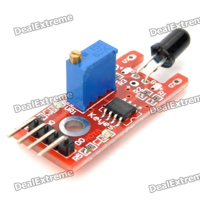
- Arduino GND --> Module G
- Arduino +5V --> Module +
- Arduino digital 4 --> Module D0
- Arduino A3 --> Module A0
//Example for KY-026
//TkkrLab
int Led = 13 ;// define LED Interface
int buttonpin = 3; // define the flame sensor interface
int analoog = A3; // define the flame sensor interface

int val ;// define numeric variables val
float sensor; //read analoog value

void setup() {
  pinMode(Led, OUTPUT) ;// define LED as output interface
  pinMode(buttonpin, INPUT) ;// output interface defines the flame sensor
  pinMode(analoog, INPUT) ;// output interface defines the flame sensor
  Serial.begin(9600);
}

void loop() {
  sensor = analogRead(analoog);
  Serial.println(sensor);  // display tempature

  val = digitalRead(buttonpin) ;// digital interface will be assigned a value of 3 to read val
  if (val == HIGH) { // When the flame sensor detects a signal, LED flashes
    digitalWrite(Led, HIGH);
  } else {
    digitalWrite(Led, LOW);
  }
  delay(1000);
}
Magic light cup module KY-027
Magic Light Cup modules are easy to Interactive Technology Division developed a can and ARDUINO interactive modules, PWM dimming principle is to use the principle of two modules brightness changes. Mercury switches provide a digital signal that triggers the PWM regulator, through the program design, We can see the light like two cups filled with the effect of shuffling back and forth.
int LedPinA = 5;
int LedPinB = 6;
int ButtonPinA = 7;
int ButtonPinB = 4;
int buttonStateA = 0;
int buttonStateB = 0;
int brightness = 0;
void setup() {
  pinMode(LedPinA, OUTPUT);
  pinMode(LedPinB, OUTPUT);
  pinMode(ButtonPinA, INPUT);
  pinMode(ButtonPinB, INPUT);
}
void loop() {
  buttonStateA = digitalRead(ButtonPinA);
  if (buttonStateA == HIGH && brightness! = 255) {
    brightness++;
  }
  buttonStateB = digitalRead(ButtonPinB);
  if (buttonStateB == HIGH && brightness! = 0) {
    brightness--;
  }
  analogWrite(LedPinA, brightness); / / A few Guan Yuan (ii)? analogWrite(LedPinB, 255 - brightness);
  // B Yuan (ii) a few Bang?
  delay(25);
}
Temperature sensor module KY-028
Digital temperature module and a digital interface, built-in 13 LED build a simple circuit, making the temperature warning lamp 13 comes with digital interfaces of the LED, the digital temperature sensor connected digital three interfaces, when the digital temperature Sensor senses a key signal, LED lights, otherwise off.
int Led = 13 ;/ / define LED Interface
int buttonpin = 3; / / define the digital temperature sensor interface
int val ;/ / define numeric variables val
void setup() {
  pinMode(Led, OUTPUT) ;/ / define LED as output interface
  pinMode(buttonpin, INPUT) ;/ / define digital temperature sensor output interface
}
void loop() {
  val = digitalRead(buttonpin) ;/ / digital interface will be assigned a value of 3 to read val
  if (val == HIGH) { // when the digital temperature sensor detects a signal, LED flashes
    digitalWrite(Led, HIGH);
  } else {
    digitalWrite(Led, LOW);
  }
}
Yin Yi 2-color LED module 3MM KY-029
// Arduino test code:
int redpin = 11; / / select the pin for the red LED
int bluepin = 10; / / select the pin for the blueLED
int val;
void setup() {
  pinMode(redpin, OUTPUT);
  pinMode(bluepin, OUTPUT);
  Serial.begin(9600);
}
void loop() {
  for (val = 255; val> 0; val -) {
    analogWrite(11, val);
    analogWrite(10, 255-val);
    delay(15);
  }
  for (val = 0; val <255; val + +) {
    analogWrite(11, val);
    analogWrite(10, 255-val);
    delay(15);
  }
  Serial.println(val, DEC);
}
Hit sensor module KY-031
13 knock sensor module and a digital interface, built-in LED build a simple circuit to produce percussion flasher. 13 Interface comes with digital LED, will knock sensor connected digital 3 interface, when percussion sensor senses Measure To percussive signals, LED flashing light.
int Led = 13 ;/ / define LED Interface
int Shock = 3 / / define the percussion Sensor Interface
int val ;/ / define numeric variables val
void setup() {
  pinMode(Led, OUTPUT) ;/ / define LED as output interface
  pinMode(Shock, INPUT) ;/ / define knock sensor output interface
}
void loop() {
  val = digitalRead(Shock); // read digital interface is assigned a value of 3 val
  if (val == HIGH) { // When the percussion when the sensor detects a signal, LED flashes
    digitalWrite(Led, LOW);
  } else {
    digitalWrite(Led, HIGH);
  }
}
- http://henrysbench.capnfatz.com/henrys-bench/keyes-ky-031-arduino-knock-impact-sensor-manual-and-tutorial/
Obstacle avoidance sensor module KY-032
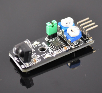
Specifications
- Working voltage: DC 3.3V-5V
- Working current: = 20mA
- Operating temperature: -10 ? - +50 ?
- detection distance :2-40cm
- IO Interface: 4-wire interfaces (- / + / S / EN)
- Output signal: TTL level (low level there is an obstacle, no obstacle high)
- Adjustment: adjust multi-turn resistance
- Effective angle: 35 °
- Size: 28mm × 23mm
- Weight Size: 9g
Here we use the obstacle avoidance module and a digital interface, built-in 13 LED build a simple circuit, making avoidance warning lamp, the obstacle avoidance Sensor Access Digital 3 interface, when obstacle avoidance sensor senses a signal, LED light, and vice versa off.
int Led = 13 ;// define LED Interface
int buttonpin = 3; // define the obstacle avoidance sensor interface
int val ;// define numeric variables val
void setup() {
  pinMode(Led, OUTPUT) ;// define LED as output interface
  pinMode(buttonpin, INPUT) ;// define the obstacle avoidance sensor output interface
}
void loop() {
  val = digitalRead(buttonpin) ;// digital interface will be assigned a value of 3 to read val
  if (val == HIGH) { // When the obstacle avoidance sensor detects a signal, LED flashes
    digitalWrite(Led, HIGH);
  } else {
    digitalWrite(Led, LOW);
  }
}
Links úteis:
Hunt sensor module KY-033
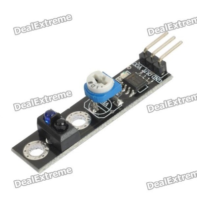
Analog magnetic sensor module and a digital interface, built-in 13 LED build a simple circuit to produce a magnetic flash Makers.13 comes with digital interfaces of the LED, the analog magnetic sensor connected to the power board analog 5 ARDUINO Interfaces, when analog magnetic sensor to a signal, LED lights, otherwise the lights out.
int sensorPin = A5; / / select the input pin
int ledPin = 13; / / select the pin for the LED
int sensorValue = 0; / / variable to store the value coming from the
sensor
void setup() {
  pinMode(ledPin, OUTPUT);
  Serial.begin(9600);
}
void loop() {
  sensorValue = analogRead(sensorPin);
  digitalWrite(ledPin, HIGH);
  delay(sensorValue);
  digitalWrite(ledPin, LOW);
  delay(sensorValue);
  Serial.println(sensorValue, DEC);
}
Automatic flashing colorful LED module KY-034
Specifications:
- Product Type: LED
- Product Model: YB-3120B4PnYG-PM
- Shape: Round LED 5mm DIP type
- Color: pink yellow green (high brightness)
- Lens type: white mist
- Standard Forward Voltage :3.0-4 .5 V
/*
Blink
Turns on an LED on for two second, then off for two second, repeatedly.
This example code is in the public domain.
* /
void setup() {
  // Initialize the digital pin as an output.
  // Pin 13 has an LED connected on most Arduino boards:
  pinMode(13, OUTPUT);
}
void loop() {
  digitalWrite(13, HIGH); / / set the LED on
  delay(2000); / / wait for a second
  digitalWrite(13, LOW); / / set the LED off
  delay(2000); / / wait for a second
}
Class Bihor magnetic sensor KY-035
KY-035 is an analog magnetic field sensor module. The strength of the field is given by an analog voltage at the signal pin of the module KY-035. The sensor is connected to gnd and 5V of the Arduino board. The output voltage is measured by analog pin A5 on the Arduino board. The example program measures the output voltage of the sensor en presents the measured value in the serial monitor of the Arduino. The led on the board flashes in a speed depending on the strength of the magnetic field. With a small magnet this can be demonstrated.
Connecting to the Arduino:
- Pin - = GND, connect to GND of the Arduino
- Pin (middle pin) +5 V, connect to Arduino +5 V
- Pin S signal, connect to Arduino pin A5
- Power consumption sensor, 8 mA
/*
KY-035 Hall analog sensor
*/

int sensorPin = A5;    // select the input pin
int ledPin = 13;       // select the pin for the LED
int sensorValue = 0;   // variable to store the value coming from the sensor

void setup() {
  pinMode(ledPin, OUTPUT);
  Serial.begin(9600);
}

void loop() {
  sensorValue = analogRead(sensorPin);
  digitalWrite(ledPin, HIGH);
  delay(sensorValue);
  digitalWrite(ledPin, LOW);
  delay(sensorValue);
  Serial.println(sensorValue, DEC);
}
Metal touch sensor module KY-036
Metal Touch Interface module and number 13 comes with LED build a simple circuit to produce a touch cue lights 13 comes with digital interfaces of the LED, the metal touch sensor connected digital three interfaces, when a metal touch Sensor senses a key signal, LED ights, otherwise off.
int Led = 13 ;/ / define LED Interface
int buttonpin = 3; / / define Metal Touch Sensor Interface
int val ;/ / define numeric variables val
void setup() {
  pinMode(Led, OUTPUT) ;/ / define LED as output interface
  pinMode(buttonpin, INPUT) ;/ / define metal touch sensor output interface
}
void loop() {
  val = digitalRead(buttonpin) ;/ / digital interface will be assigned a value of 3 to read val
  if (val == HIGH) { // When the metal touch sensor detects a signal, LED flashes
    digitalWrite(Led, HIGH);
  } else {
    digitalWrite(Led, LOW);
  }
}
Sensitive microphone sensor module KY-037
int Led=13;//??LED ??
int buttonpin=3 //?????D0??
int val;//??????val
void setup() {
  pinMode(Led,OUTPUT);//??LED ?????
  pinMode(buttonpin,INPUT);//?????D0?????
}

void loop() {
  val=digitalRead(buttonpin);//?????3??????val
  if(val==HIGH) {
    digitalWrite(Led,HIGH)
  } else {
    digitalWrite(Led,LOW)
  }
}
int sensorPin = A5;    // select the input pin for the potentiometer
int ledPin = 13;      // select the pin for the LED
int sensorValue = 0;  // variable to store the value coming from the sensor

void setup() {
  pinMode(ledPin, OUTPUT);
  Serial.begin(9600);
}

void loop() {
  sensorValue = analogRead(sensorPin);
  digitalWrite(ledPin, HIGH);
  delay(sensorValue);
  digitalWrite(ledPin, LOW);
  delay(sensorValue);
  Serial.println(sensorValue, DEC);
}
Microphone sound sensor module KY-038

Microphone sound detection module For sound detection Module has two outputs: AO, analog output, real-time output voltage signal of the microphone DO, when the sound intensity reaches a certain threshold, the output high and low signal The threshold-sensitivity can be adjusted via potentiometer on the sensor
Connecting to the Arduino
- Pin + to Arduino 5+
- Pin - to Arduino -
- Pin A0 to Arduino A0 (for analog program)
- Pin D0 to Arduino 13 (for digital program)
Example code: Digital output
int Led = 13 ;// define LED Interface
int buttonpin = 3; // define D0 Sensor Interface
int val = 0;// define numeric variables val

void setup() {
  pinMode(Led, OUTPUT) ;// define LED as output interface
  pinMode(buttonpin, INPUT) ;// output interface D0 is defined sensor
}

void loop() {
  val = digitalRead(buttonpin);// digital interface will be assigned a value of pin 3 to read val
  if (val == HIGH) { // When the sound detection module detects a signal, LED flashes
    digitalWrite(Led, HIGH);
  } else {
    digitalWrite(Led, LOW);
  }
}
Example Code : analog outputs
int sensorPin = A0; // select the input pin for the potentiometer
int ledPin = 13; // select the pin for the LED
int sensorValue = 0; // variable to store the value coming from the sensor

void setup() {
  pinMode(ledPin, OUTPUT);
  Serial.begin(9600);
}

void loop() {
  sensorValue = analogRead(sensorPin);
  digitalWrite(ledPin, HIGH);
  delay(sensorValue);
  digitalWrite(ledPin, LOW);
  delay(sensorValue);
  Serial.println(sensorValue, DEC);
}
Detect the heartbeat module KY-039
This project uses bright infrared (IR) LED and a phototransistor to detect the pulse of the finger, a red LED flashes with each pulse. Pulse monitor works as follows: The LED is the light side of the finger, and phototransistor on the other side of the finger, phototransistor used to obtain the flux emitted, when the blood pressure pulse by the finger when the resistance of the photo transistor will be slightly changed. The project's schematic circuit as shown, We chose a very high resistance resistor R1, because most of the light through the finger is absorbed, it is desirable that the phototransistor is sensitive enough. Resistance can be selected by experiment to get the best results. The most important is to keep the shield stray light into the phototransistor. For home lighting that is particularly important because the lights at home mostly based 50HZ or 60HZ fluctuate, so faint heartbeat will add considerable noise. When running the program the measured values are printed. To get a real heartbeat from this could be challenging.
Connecting to the Arduino
- Sensor pin S connect to Arduino pin Analoog 0 / A0
- Sensor pin + (middle pin) connect to Arduino pin 5+
- Sensor pin - connect to Arduino pin GND
Example Code
// Pulse Monitor Test Script
int sensorPin = 0;
double alpha = 0.75;
int period = 100;
double change = 0.0;
double minval = 0.0;
void setup() {
  Serial.begin(9600);
}
void loop() {
  static double oldValue = 0;
  static double oldChange = 0;

  int rawValue = analogRead(sensorPin);
  double value = alpha * oldValue + (1 - alpha) * rawValue;

  Serial.print(rawValue);
  Serial.print(",");
  Serial.println(value);
  oldValue = value;

  delay(period);
}
Rotary encoder module KY-040
The Keyes KY-040 rotary encoder is a rotary input device (as in knob) that provides an indication of how much the knob has been rotated AND what direction it is rotating in. It’s a great device for stepper and servo motor control. You could also use it to control devices like digital potentiometers.
Rotary encoder module By rotating the rotary encoder can be counted in the positive direction and the reverse direction during rotation of the output pulse frequency, unlike rotary potentiometer counter, which Species rotation counts are not limited. With the buttons on the rotary encoder can be reset to its initial state, that starts counting from 0. How it works: incremental encoder is a displacement of the rotary pulse signal is converted to a series of digital rotary sensors. These pulses are used to control Angular displacement. In Eltra angular displacement encoder conversion using a photoelectric scanning principle. Reading system of alternating light transmitting window and the window is not Consisting of radial indexing plate (code wheel) rotating basis, while being an infrared light source vertical irradiation light to the code disk image onto the receiving On the surface. Receiver is covered with a diffraction grating, which has the same code disk window width. The receiver's job is to feel the rotation of the disc Resulting changes, and change the light into corresponding electrical changes. Then the low-level signals up to a higher level, and generates no interference Square pulse, which must be processed by electronic circuits. Reading systems typically employ a differential manner, about the same but the phase difference of the two waveforms Different by 180 ° compared to the signal in order to improve the quality and stability of the output signal. Reading is then the difference between the two signals formed on the basis, Thus eliminating the interference. Incremental encoder Incremental encoders give two-phase square wave, the phase difference between them 90 °, often referred to as A and B channels. One of the channels is given and speed-related Information, at the same time, by sequentially comparing two channel signals, the direction of rotation of the information obtained. There is also a special signal called Z or Zero channel, which gives the absolute zero position encoder, the signal is a square wave with the center line of channel A square wave coincide. Clockwise counterclockwise A B 1 1 0 1 0 0 1 0 1 1 1 0 0 0 0 1
Incremental encoder accuracy depends on the mechanical and electrical two factors, these factors are: Raster indexing error, disc eccentricity, bearing eccentricity, e-reading Several means into the optical portion of the errors and inaccuracies. Determine the encoder resolution is measured in electrical degrees, the encoder accuracy depends Set the pulse encoder generates indexing. The following electrical degrees with a 360 ° rotation of the shaft to said machine, and rotation of the shaft must be a full week of Period. To know how much electrical equivalent of the mechanical angle of 360 degrees can be calculated with the following formula: Electrical 360 = Machine 360 ° / n ° pulses / revolution Figure: A, B commutation signals Encoder indexing error is the electrical angle of the unit two successive pulse maximum offset to represent. Error exists in any encoder, which Is caused by the aforementioned factors. Eltra encoder maximum error is ± 25 electrical degrees (declared in any condition), equivalent to the rated Offset values ± 7%, as the phase difference 90 ° (electrical) of the two channels of the maximum deviation ± 35 electrical degrees is equal to ± 10% deviation left Ratings Right. UVW incremental encoder signals In addition to the conventional encoder, there are some other electrical output signal with integrated incremental encoder. And UVW signals The integrated incremental encoder that instance, it is usually applied to the AC servo motor feedback. These magnetic signals generally appear in the AC servo motor Machine, UVW through the simulation of the magnetic signal is generally of the original function and design. In Eltra encoder, these optical signals are UVW Methods of generating, and three square wave form, are offset from each other 120 °. In order to facilitate starting the motor, the control of the starter motor to be To these the correct signal. The UVW poles in the machine axis rotation pulses repeated many times, because they directly depend on the connected electrical Machine number of poles, and for 6 or more pole motor UVW signal. See also Youtube video
Example Code
int redPin = 2;
int yellowPin = 3;
int greenPin = 4;
int aPin = 6;
int bPin = 7;
int buttonPin = 5;
int state = 0;
int longPeriod = 5000; // Time at green or red
int shortPeriod = 700; // Time period when changing
int targetCount = shortPeriod;
int count = 0;
void setup() {
  pinMode(aPin, INPUT);
  pinMode(bPin, INPUT);
  pinMode(buttonPin, INPUT);
  pinMode(redPin, OUTPUT);
  pinMode(yellowPin, OUTPUT);
  pinMode(greenPin, OUTPUT);
}
void loop() {
  count++;
  if (digitalRead(buttonPin)) {
    setLights (HIGH, HIGH, HIGH);
  } else {
    int change = getEncoderTurn ();
    int newPeriod = longPeriod + (change * 1000);
    if (newPeriod  >= 1000 && newPeriod <= 10000) {
      longPeriod = newPeriod;
    }
    if (count> targetCount) {
      setState ();
      count = 0;
    }
  }
  delay(1);
}
int getEncoderTurn () {
  // Return -1, 0, or +1
  static int oldA = LOW;
  static int oldB = LOW;
  int result = 0;
  int newA = digitalRead(aPin);
  int newB = digitalRead(bPin);
  if (newA != oldA || newB != oldB) {
    //Something has changed
    if (oldA == LOW && newA == HIGH) {
      result = - (oldB * 2 - 1);
    }
  }
  oldA = newA;
  oldB = newB;
  return result;
}
int setState () {
  if (state == 0) {
    setLights (HIGH, LOW, LOW);
    targetCount = longPeriod;
    state = 1;
  } else if (state == 1) {
    setLights (HIGH, HIGH, LOW);
    targetCount = shortPeriod;
    state = 2;
  } else if (state == 2) {
    setLights (LOW, LOW, HIGH);
    targetCount = longPeriod;
    state = 3;
  } else if (state == 3) {
    setLights (LOW, HIGH, LOW);
    targetCount = shortPeriod;
    state = 0;
  }
}
void setLights (int red, int yellow, int green) {
  digitalWrite(redPin, red);
  digitalWrite(yellowPin, yellow);
  digitalWrite(greenPin, green);
}
Links úteis: